Introduction
This is a sugested procedure for modifying the VXT airbox. Power tools have been used but the same result can be achieved using hand tools.
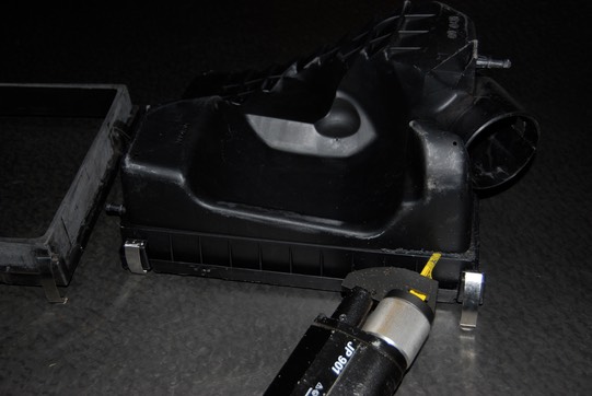
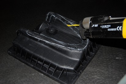
Step 1
Cut airbox as shown. An air saw is ideal for this.
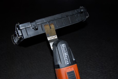
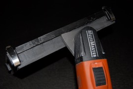
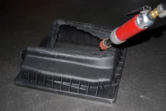
Step 2
Remove fillets. An oscilating saw is being used.
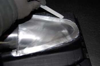
Step 3
Sand smooth. This operation gives a good key for the adhesive/ sealant to be used.
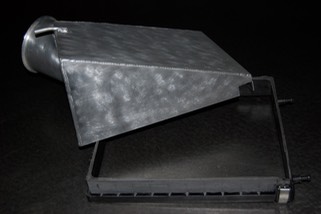
Step 4
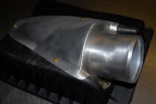
Parts ready for assembly
Step 5
Position airbox outlet as shown and mark with chalk.
Step 6
Chalk within the line the width of the flange. Cut to this line and remove the existing outlet.
Step 7
The edge can be cleaned up using a die grinder.
Step 8
The parts have been assembled by drilling holes and using nuts and bolts. The bolts should be fitted from the inside and should have shallow heads so as not to foul the filter. Nylock nuts should be used or the protruding thread should be peened to prevent the fasteners coming undone during service!
Step 9
Now that the dry build is satisfactory it can be disembled, degreased, the aluminium joint faces can also be abraded and then reassembled with a bead of Sikoflex 221 sealing mastic.
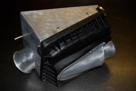
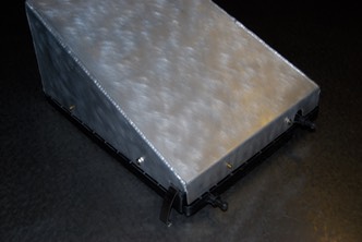
Finished Assembled Airbox
The finished airbox. Ensure there is no debris inside that can ingress into the induction tract.